Dry Joint Exhaust – How to Position the Restrictor vs Full Flow Gasket
PPT’s Engineering Background with Marine Exhaust Systems
Due to our engineering background at MerCruiser with Marine Exhaust Systems we’re regularly asked about the positioning of the Dry Joint Exhaust System full flow gasket versus the restrictor gasket, along with which directional orientation is correct for the restrcitor hole itself. Without going into too much detail this article will give you some background regarding the design intent of this system. Having been engineers for Mercruiser throughout the development of the Dry Joint Exhaust system, as well as the patenting (select link to view the patents) to release into these systems into production we have a very thorough background to address these questions.
Marine Exhaust Manifolds – Warm Manifold Design
The purpose of the restrictor hole is based on the desire to run the manifolds warm therefore preventing condensation from collecting in the exhaust manifolds. The intended design is such that the excess raw water supplied to the enigne is routed out through the fittings which are located in the exhaust elbows. Therefore the surface area exposed to the cold bypass water is minimized to only the exhaust elbows and not the manifolds or spacers. After the engine thermostat opens the heated water that flowed through the engine is then routed through the thermostat and out of the system while exiting through the fittings located in the bottom of the exhaust manifolds.
Purpose of the Restrictor Hole Design
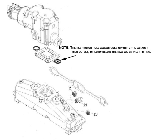
The purpose of the restrictor hole is to prevent the cold bypass water as it enters the exhaust elbow, from back-flowing down and into the manifolds. If the restrictor hole is positioned incorrectly the cold bypass water will flow downward into the manifold and prevent the manifold temperatures from heating up enough to prevent condensation.
When Your Exhaust System is Equipped With Exhaust Spacers
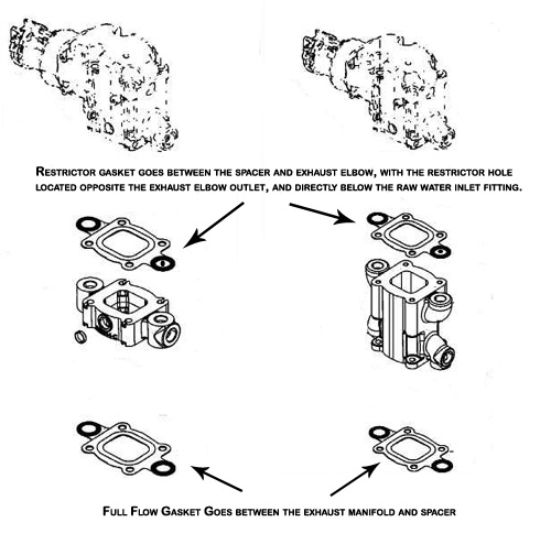
It is most commonly desired to minimize the total amount of surface area that gets exposed to the cold bypass water. With this in mind the desired approach is to put the restrictor gasket just below the exhaust elbow. Therefore no matter whether you run the 3″ or 6″ spacer the your cold bypass water is still limited to only the surface area of the exhaust elbow and not the exhaust manifolds. Then the exhaust manifolds and spacers get exposed to the heated water after it exits the thermostat.