
Mercruiser 4.3L V6 Exhaust Manifolds
Topic: Mercruiser Exhaust Manifolds for the 4.3L V6 Engine (Single Piece vs Two Piece)
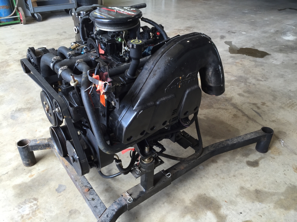
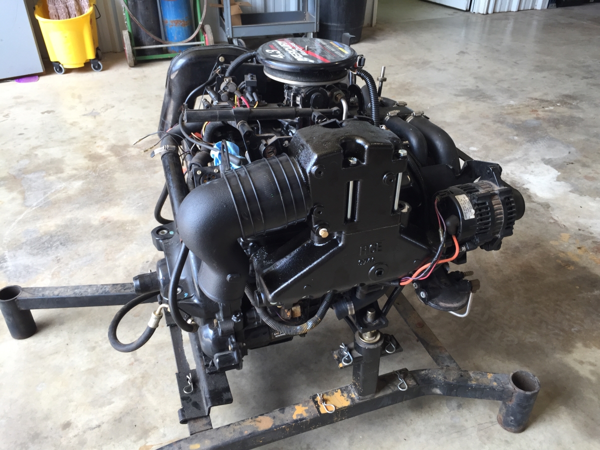
Question: My existing Mercruiser 4.3L V6 engine has a manifold and elbow/riser that is combined in one piece. However I cannot seem to locate the exact replacement for this manifold. Can I simply replace this with the older style 2 piece manifold and riser?
Background
Along with the release of the 1996 “Vortec” model 4.3L V6 engines (Read More) Mercruiser made significant changes to the exhaust system. The purpose of this technical article is to address the history behind these exhaust system changes, as well as provide directions about how you can replace the discontinued components on your existing Mercrusier 4.3L V6 engine.
The number one reason behind the decision to switch to a SINGLE PIECE exhaust manifold was to offset the increased cost of the new Vortec 4.3L V6 base engine from General Motors. By eliminating the INTERMEDIATE EXHAUST ELBOW along with the 2nd required EXHAUST BELLOWS MerCruiser was able to save approximately $50/engine. When you factor in the popularity of the Mercrusier 4.3L V6 Engine that represented approximately 25k annual units being produced you see how quickly the cost savings $’s added up at $50 x 25,000 = BIG $. However, as quickly as the potential savings could add up the opportunity was equally present for huge losses if problems were encountered in production that prevented delivery of the product.
Challenges to the Mercruiser Single Piece Exhaust Manifold Design
Exhaust Alignment – There were a variety of difficulties in producing this significantly more complex Single Piece Manifold casting. However, other overall product challenges presented themselves primarily as follows;
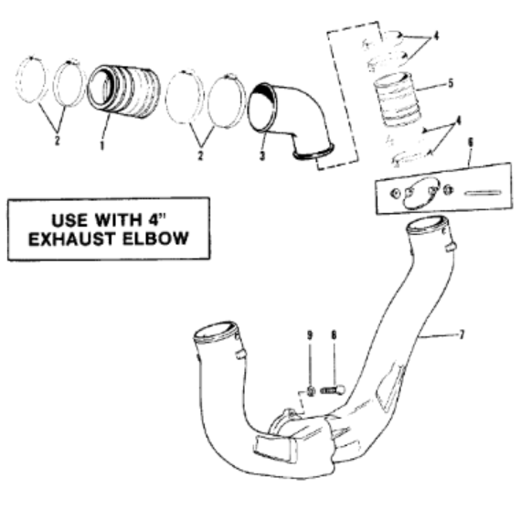
1) Alignment – How to maintain alignment between the exhaust outlet and the inlet of the Bullhorn (also known as the Y-Pipe). This was a huge challenge when you realize the Y-Pipe is connected and floats with the plane of the “Outer Transom Plate” whereas the engine is located off of and floats with the plane of the “Inner Transom Plate”. Therefore, the potential not only for the normal dimensional variation within the Exhaust Manifold casting and machining itself but also the wide variation of Transom Thicknesses and Transom Angles with so many different boat builders. With this challenge at hand Mercruiser designed a new Y-Pipe that had a larger opening to accommodate for this positional variation. Therefore, the engine/exhaust manifold outlet could fluctuate from front to rear however the outlet would always fall within the enlarged opening of this new Y-Pipe p/n 807130A7 (Read More). This then required a new Exhaust Bellows p/n 32-807458T (Read More) as well as a new Water Shutter p/n 807166A2 (Read More) to accommodate the larger Y-Pipe opening.
2) Casting Method – The existing 2 piece exhaust manifolds were being cast using the traditional “Green Sand” method of producing dual-wall castings. However, this manufacturing process was not adequate for producing the much larger one piece exhaust manifold and riser combination casting. Therefore, the casting method chosen for this new design was the Lost Foam or Evaporative Casting process. This process requires producing a Foam pattern that is representative of the part being produced, which is then inserted into the casting flask while being surrounded by core sand. Molten iron is then poured into the flask and burns out the foam leaving the cast product within the core sand. Producing good Single Piece Manifolds proved very difficult even with the Lost Foam casting process as the amount of gas released by the foam patterns made the internal sand cores float through the adjoining wall thickness. To make a long story short this reulted in a high scrap rate which ultimately drove the ongoing product costs too high.
**SOLUTION
By the end of the life cycle for the Single Piece exhaust manifold there were other problems that developed which lead to the ultimate decision to abandon the design altogether. Aside from escalating product costs the other main issue with the Single Piece Exhaust design was related to more severe instances of “Water Reversion” (Read More).
Replacement 4.3L Manifolds – Painted or Coated (Read More)
Replacement 4.3L Elbow/Riser – Painted or Coated (Read More)
Complete Exhaust Manifold & Riser Kit’s – Cast Iron & Aluminum (Read More)
Part Diagrams and Schematics
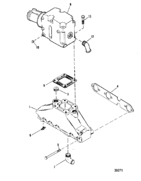
2 Piece Exhaust Manifold Diagram & Related Components (Read More)
2 Piece Exhaust Y-Pipe/Bullhorn Diagram & Related Components (Read More)
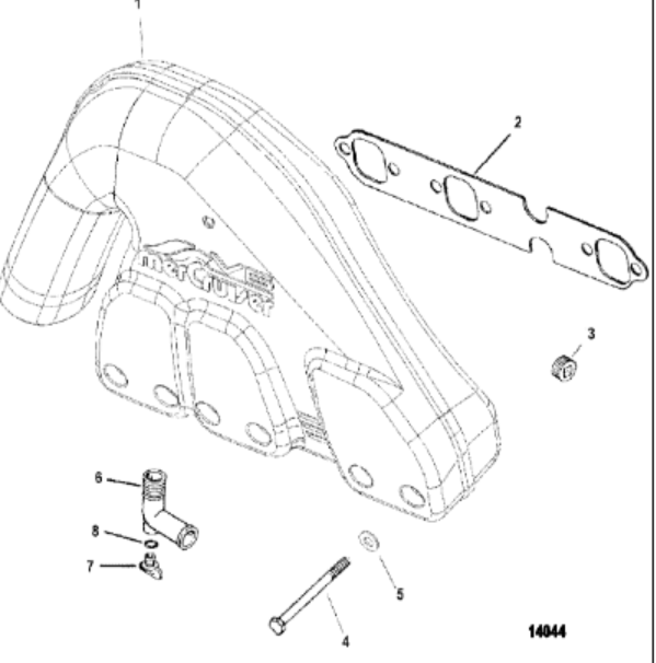
1 Piece Exhaust Manifold Diagram & Related Components (Read More)
1 Piece Exhaust Manifold Diagram & Related Components (Read More)