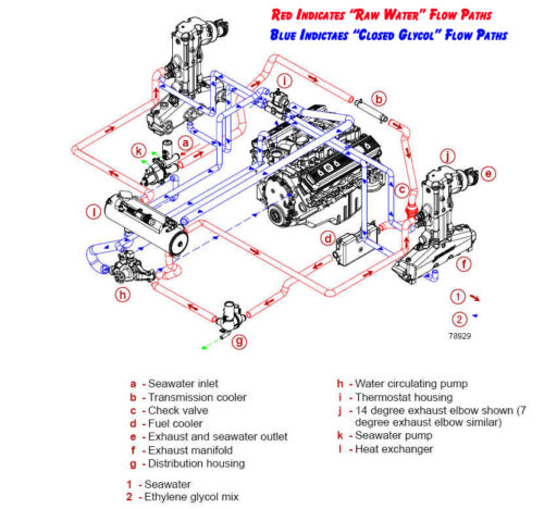
Mercruiser Closed Cooling System Flow Diagram
 |
 |
 |
CHECK INVENTORY & SHOP ONLINE: Click Here
Question: Do the Mercruiser Engines equipped with the Dry Joint Style Exhaust AND Closed Cooling systems circulate antifreeze through the exhaust manifolds?
Answer: Mercruiser has made changes over the years between 1/2 and FULL cooling systems. The driving factor for this was the same reason that always seems to govern manufacturers and their products; cost. Up until 1992 Mercruiser had almost always configured their marine cooling systems, both raw water and fresh water cooling systems, such that they included warm manifolds. However in 1992 when Mercruiser introduced the 502 mag EFI motor the intake plenum was so large that it interfered with the standard thermostat housing and therefore prevented them . Therefore Mercruiser set out to determine if there were functional issues to back up the concerns that the exhaust manifolds could not be allowed to run colder than engine temperature. Mercruiser performed a significant amount of functional testing with the cold manifold systems and the resulting effect of condensation. They determined through this testing that no functional damage resulted that could be attributed to the cold manifolds. Therefore starting in 1992 with the introduction of teh 502 Mag MPI Mercruiser offered the first of several engines with the cold manifold style cooling system.
However around the 2000 model year Mercruiser realized that the cost of warranty related to condensation induced engine damage had escalated significantly over the past 8 years and was becoming a real issue. Therefore when the 8.1L engine was released in 2001 it was determined that there was no achievable way to introduce this new engine with a warm manifold type cooling system. Therefore several specific system designs were implemented on this engine to allow it to also be released with the cold manifold type cooling system. However in 2002 the decision was made that going forward all new designs would be done while including a warm manifold cooling system unless this was just not possible.
Cooling Flow Diagram: Therefore referencing the above flow diagram we want to point out a few of the following Mercruiser specific features:
- Reference Item “C” Check Valve – This is a patented feature offered by Mercruiser. Since Mercruiser offers the easy to use Single Point Drain system’s they have to take into account that preventative features are required to prevent water entering the boat when the draining is underway. Historically this was done manually when draining was performed with the boat remaining in the water by using a manually operated ball valve.
- Reference Item “G” Distribution Housing – This patented feature is specific to Mercruiser and required to support the single point drain feature. All of the incoming water is tied into a centrally located housing which can then be used as a location for draining. Note that a derivative of this housing is used with the raw water or open cooling systems.
- Reference Item “I” Thermostat Housing – Mercruiser utilized a full flow thermostat housing that direct flow through the heat exchanger or through the bypass circuit at all times. This is a key feature of Mercruiser Cooling System in that regardless of the thermostat position, the engine always experiences 100% coolant flow. This is important to engine operating efficiency because it’s not always the coolant temperature rather the coolant flow that determines if and when detonation occurs. Therefore an engine with maximum flowrate through the cylinder heads offers the best opportunity for achieving the maximum spark timing.

